Howdy younguns!! Today y'all better get ready - here comes some knowledge at your face!
So today we learn how a motor works.
Keep in mind that even though there are a few differences from motor to motor in several machines, most work on the basic principle explained in the theory part.
Note - This article can be called a continuation of the one I did on a blender, and contains even more details of the motor in it. You can read it here.
BAM! Self promotion is the attribute of a good blogger. Good job Siddhant.
Thanks other Siddhant.
You're welcome other other Siddhant.

1.Follow the opening instructions from the blender blog.
2.Disconnect all the wires between the motor and the housing and pull the motor out.
3.Remove the 2 large screws on the top with your bare, manly hands. That instruction includes all you women out there too.

4.Pull out the top part WHILE ensuring you do not touch the small little ball at the bottom.

5.Keep the ball aside and don't lose it. Seriously. It's important.
A motor usually consists of a stator, a rotor, a bush bracket, a ball bearing, a commutator and 'the holder thingy whose name I could not find on the net'. Real professional stuff here guys.
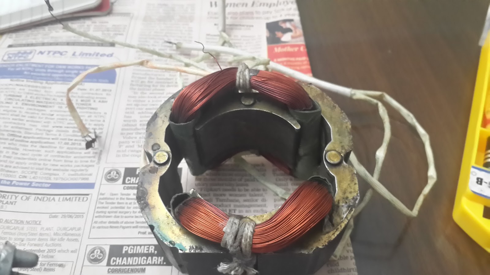
1.Stator - The 2 copper wire loops are collectively known as the stator and act as electromagnets. These have a certain number of allotted slots to them such that they produce a different magnetic field according to each. This is why it is also called the field in electrical terms. More on this in the theory.

2.Rotor - Also called an armature, it has a continuous series of windings from each bar on the commutator, which loop around the iron stack teeth(called turns in a coil) and connect to the next bar on the commutator. The winding continues to loop all the way around the armature in the same manner. Loops are either single or parallel wires(that act as conductors), and can circle multiple times around the stack teeth . Each wire is insulated with an enamel coating, isolating it from every other wire in the loop, and only terminates at a commutator bar. The turns in every coil wrap around the iron stack to create an electro-magnet.

3.Bush bracket - This part separates the rotor from it's holders so that they don't burn from the friction produced.
4.Ball bearing - This is that small little ball at the bottom of the rotor. It is placed inside the bottom holder and is allowed to move freely. This is because the rotor can move at really high speeds and so lots of friction is generated at the bottom, so this ball converts sliding motion to rolling motion, which reduces the friction substantially.It is also greased up to further reduce friction.

5.Commutator - A commutator is the part which periodically reverses the current direction between the rotor and the external circuit. It consists of a cylinder composed of multiple metal contact segments on the rotating armature of the machine. Two stationary electrical contacts called "brushes" made of a soft conductor like carbon press against the commutator, make sliding contact with successive segments of the commutator as it rotates. The windings on the armature are connected to the commutator segments.
6.The holder thingy - Even though I couldn't find this pieces' name, I'm pretty sure its not as cool as 'the holder thingy'. In fact, I'm going to file a PIL to change it's name.Not like the Indian government has anything more important on it's hands *cough*land acquisition bill*cough*(also I am aware the Indian government does not control the names of electrical parts. I am just really desperate for jokes here guys).
Anyways, this has two parts, the upper holder thingy which is right above the bush bracket and the lower holder thingy which has the ball bearing in a small cavity. These cover the rotor on both sides and have a rod passing through holding the whole motor.
1.The armature can get burnt due to short circuiting.
2.The small carbon holders can get worn out. This is because a spring is typically used with the brush, to maintain constant contact with the commutator. As the brush and commutator wear down, the spring steadily pushes the brush downwards towards the commutator. Eventually the brush wears small and thin enough that steady contact is no longer possible or it is no longer securely held in the brush holder, and so the brush must be replaced.
3.The grease in the ball bearing can get reduced, thus increasing friction and causing sparks this can also happen with the bush bearing. Why is this bad? In simple terms - fire not good, fire burn hand.
There you go.You know we here at SiddhantsblogenterprisesTM pride ourselves at our capabilities of explaining people really hard concepts, and this goes a long way in showing that.
According to Faraday’s law an emf induced in any circuit is due to the rate of change of magnetic flux linkage through the circuit.
The geometry of the brushes, commutator contacts, and rotor windings in a motor is such that when power is applied, the polarities of the energized winding and the stator magnet are misaligned, and the rotor will rotate until it is almost aligned with the stator's field magnets. As the rotor reaches alignment, the brushes move to the next commutator contacts, and energize the next winding.
So today we learn how a motor works.
Keep in mind that even though there are a few differences from motor to motor in several machines, most work on the basic principle explained in the theory part.
Note - This article can be called a continuation of the one I did on a blender, and contains even more details of the motor in it. You can read it here.
BAM! Self promotion is the attribute of a good blogger. Good job Siddhant.
Thanks other Siddhant.
You're welcome other other Siddhant.
Procedure

1.Follow the opening instructions from the blender blog.
2.Disconnect all the wires between the motor and the housing and pull the motor out.
3.Remove the 2 large screws on the top with your bare, manly hands. That instruction includes all you women out there too.

4.Pull out the top part WHILE ensuring you do not touch the small little ball at the bottom.

5.Keep the ball aside and don't lose it. Seriously. It's important.
 |
| Eat it - trust me, I read the box and NOWHERE does it say that it's a choking hazard!! Mmm....greasy... |
Different parts of the motor
A motor usually consists of a stator, a rotor, a bush bracket, a ball bearing, a commutator and 'the holder thingy whose name I could not find on the net'. Real professional stuff here guys.
1.Stator - The 2 copper wire loops are collectively known as the stator and act as electromagnets. These have a certain number of allotted slots to them such that they produce a different magnetic field according to each. This is why it is also called the field in electrical terms. More on this in the theory.
2.Rotor - Also called an armature, it has a continuous series of windings from each bar on the commutator, which loop around the iron stack teeth(called turns in a coil) and connect to the next bar on the commutator. The winding continues to loop all the way around the armature in the same manner. Loops are either single or parallel wires(that act as conductors), and can circle multiple times around the stack teeth . Each wire is insulated with an enamel coating, isolating it from every other wire in the loop, and only terminates at a commutator bar. The turns in every coil wrap around the iron stack to create an electro-magnet.

4.Ball bearing - This is that small little ball at the bottom of the rotor. It is placed inside the bottom holder and is allowed to move freely. This is because the rotor can move at really high speeds and so lots of friction is generated at the bottom, so this ball converts sliding motion to rolling motion, which reduces the friction substantially.It is also greased up to further reduce friction.

5.Commutator - A commutator is the part which periodically reverses the current direction between the rotor and the external circuit. It consists of a cylinder composed of multiple metal contact segments on the rotating armature of the machine. Two stationary electrical contacts called "brushes" made of a soft conductor like carbon press against the commutator, make sliding contact with successive segments of the commutator as it rotates. The windings on the armature are connected to the commutator segments.
|
| Here the commutator is the lower copper coloured cylinder |
 |
| A carbon holder or a brush with a spring attached to it |
6.The holder thingy - Even though I couldn't find this pieces' name, I'm pretty sure its not as cool as 'the holder thingy'. In fact, I'm going to file a PIL to change it's name.Not like the Indian government has anything more important on it's hands *cough*land acquisition bill*cough*(also I am aware the Indian government does not control the names of electrical parts. I am just really desperate for jokes here guys).
Anyways, this has two parts, the upper holder thingy which is right above the bush bracket and the lower holder thingy which has the ball bearing in a small cavity. These cover the rotor on both sides and have a rod passing through holding the whole motor.
 |
| Cavity in the lower holder |
Problems that could come up
1.The armature can get burnt due to short circuiting.
2.The small carbon holders can get worn out. This is because a spring is typically used with the brush, to maintain constant contact with the commutator. As the brush and commutator wear down, the spring steadily pushes the brush downwards towards the commutator. Eventually the brush wears small and thin enough that steady contact is no longer possible or it is no longer securely held in the brush holder, and so the brush must be replaced.
3.The grease in the ball bearing can get reduced, thus increasing friction and causing sparks this can also happen with the bush bearing. Why is this bad? In simple terms - fire not good, fire burn hand.
There you go.You know we here at SiddhantsblogenterprisesTM pride ourselves at our capabilities of explaining people really hard concepts, and this goes a long way in showing that.
Theory
According to Faraday’s law an emf induced in any circuit is due to the rate of change of magnetic flux linkage through the circuit.
The geometry of the brushes, commutator contacts, and rotor windings in a motor is such that when power is applied, the polarities of the energized winding and the stator magnet are misaligned, and the rotor will rotate until it is almost aligned with the stator's field magnets. As the rotor reaches alignment, the brushes move to the next commutator contacts, and energize the next winding.
Here the relative velocity between the rotating flux and
static rotor conductor is the cause of
current generation; hence as per Lenz's law (If an induced current flows, its direction is always such that it will oppose the change which produced it.), the rotor will rotate in the
same direction to reduce the cause i.e. the relative velocity.
It must be noted that the rotor speed never reaches the
synchronous speed produced by the stator - if the speeds equal, there would be
no such relative velocity, no emf induction in the rotor, thus no food for the tummy, because who honestly will
manually make food right? I mean come on, this is 2015.
Also, the rotation of the magnetic field in an induction
motor has the advantage that no electrical connections need to be made to the
rotor.
Note - Commutators usually have more than 2 poles. This avoids ‘dead spots' - if the rotor is exactly at the middle of its rotation (perfectly aligned with
the field magnets), it will get "stuck" there. Meanwhile, with a
two-pole motor, there is a moment where the commutator shorts out the power
supply (i.e., both brushes touch both commutator contacts simultaneously). This
would be bad for the power supply, waste energy, and damage motor components as
well. Yet another disadvantage of such a simple motor is that it would exhibit
a high amount of torque "ripple" (the amount of torque it could
produce would be dependant upon the position of the rotor).
 |
| Shut up, it's my drawing and I can use it as many times as I want |
No comments:
Post a Comment