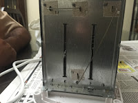
Hey it's not a blog I've written if it doesn't start off by killing you.
Procedure
2.Remove all the screws from the bottom of the toaster.
3.Carefully remove the cover by pulling it out from the side of the slit.
Different parts of a toaster
1.Housing - This is the outer part that, in this case, is made from a heat resistant plastic, although many can be made from aluminium. It is carefully designed so that maximum heat goes to the bread.
2.Spring loaded tray - This is the holding tray made of stainless steel in which the bread rests while heating. A common misconception is that this is the part which actually heats the bread. Of course this is not true as if so the bread would always have burnt marks on it, which is not the case.
3.Nichrome wires or the element - See those thin horizontal lines in the picture above? These are the actual wires that heat the element. Wrapped around mica sheets in continuous spirals, these are specially shaped, as instead of having a circular cross section, they are simply made flat.Why so? Well, normal wires, being circular, dissipate the heat from the energy they lose equally in all directions. But we need the energy to be dissipated in only one direction - that of the bread. So, making them flat resolves our problem.
4.Mica sheets - As the element has to be wrapped around it, this part is heat resistant, fire proof, and non conductive. Usually, 3 of these are present in a toaster.
5.Connectors - Present on the sides of the grill, these connect the three parts of the element in a series connection and are usually made of tungsten or canthel.
6.Printed Circuit Board - Called a PCB for short, this piece has multiple resistors, capacitors, transistors and potentiometers. More on these components can be found here.
7.Operating lever - This is the section which activates the circuit. It includes the PCB, an electromagnet an iron piece, a copper piece and the element together. This is a long process and is discussed in the theory part.
Problems that could come up
1.Element can get burnt - The nichrome wire, due to short circuiting, can get burnt, in which case it needs to be replaced.
2.Operating lever can become defective - As discussed in the theory part, the switch plate has multiple items inside it, thus it would not be surprising if one part turned faulty, compromising the whole circuit. Check the individual parts carefully.
3.PCB stops working - It can be that a small resistor, potentiometer or capacitor falls off the board, as the connections are not that strong to begin with. In such a scenario try to solder it back on with a soldering iron, or if you don't have one, try going to the corner of a room, crying and eating a tub of chocolate pudding. Works for me.
 |
| Mmmm....references.... |
Theory
Alright, so the knob which is turned to set the time is actually connected to the PCB which then allows electricity to flow through an electromagnet - the handle which is pulled down has a small rectangular piece inside, which also goes down with it. This piece has an iron piece connected to it on one side, that gets stuck to the electromagnet (that gets activated when the toaster is turned on), and a copper piece on the other, which by going down fills a gap in the circuit thus connecting the wires to the element, giving it electricity. As the timer approaches 0, the PCB stops the flow of electricity through the electromagnet, which lets go of the iron piece and thus the copper piece too, and breaks the circuit.
 |
| The black piece is the gap the copper piece connects |
 |
| The electromagnet |
 |
| The operating switch when activated. Here the iron piece gets stuck to the electromagnet and keeps the whole handle down |
Here are some numbers I just had lying around that I could not use. I don't know what you'd do with it, but.....
1.The PCB uses 12 V
2.The tungsten or the canthel connector has a cross sectional area of 0.3 or 0.4 mm2
3.The element has a resistance of 80 Ω. Guess how long it took me to add that symbol to my language keyboard....... And now I realise I could have copy/pasted it from the internet GODDAMMIT.
4.The element has a current of around 2.75A. This can actually be calculated as V = IR. In India the household voltage value is 220V and we already know the resistance is 80Ω.


No comments:
Post a Comment